|
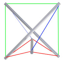
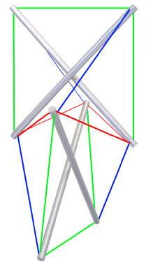
The kite frame is transformed into a true tensegrity structure by introducing a third strut which is done by replacing one of the original “edge” tension lines (in green) with four new lines shown in red. These four perform as “slings” which suspend the new strut. The three-strut structure must now be made stable by adding two additional lines (draws), those shown in blue. The “draw” tendons go from the ends of the new, third, strut to the far ends of the original pair; to those ends that will draw the kite struts away from one another. Connected to the wrong two ends the draw lines will only force the kite struts into firmer contact and fail to achieve a floating compression structure. It is essential in this simple structure, as in all tensegrity structures, to establish the optimum lengths for the tension members so that the work will be firm and tightly prestressed. This can only be done by successive adjustments, by trial and error. If the length of one line is changed the tension on all lines are effected. As a general rule the draw lines are the primary means for increasing or relaxing the prestressing of a tensegrity structure. As with most rules, there are a variety of exceptions. This construction process, adding parts one by one, has now ransformed the basic kite frame into a proper three-strut tensegrity module.. It is structurally the same as the three-way module shown on page 15. Only their shapes and symmetries are altered by size adjustments of the tendons and struts. Replacing A Single Strut With An X-Module In the figure to the right, the third strut that was introduced in the figure above is itself replaced by a second kite frame; “slings” in red, “draws” in blue. This new assembly of two “x-modules” represents the first step in a construction process — adding module after module — that can be expanded indefinitely. Each open quadrant of any module offers a place to connect yet another x-module. |

A kite-frame transformed into a tensegrity structure
A two-module x-column |
